 Systems Architecture Diagrams Types
Examples
- Structural Flow Diagram
- Application components flow
- System/Network Diagram
- Network diagrams, with Regions and Availability Zones
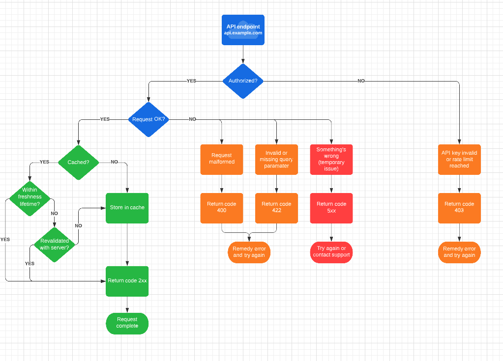
- Flow Chart
- Good for branching off decisions
- Sequence Diagram
- Great for request-response tracking such as with Auth
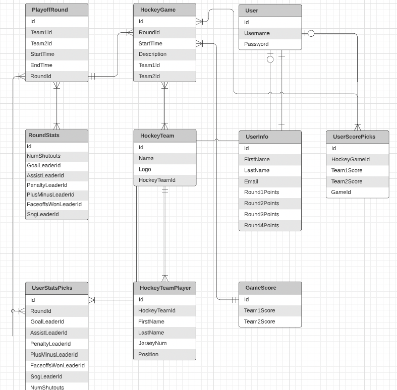
- UML Diagram
- Useful for data models and databases.
- Class Diagram
- Similar to UML
- Object Diagram
- Application level object classes
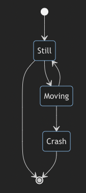
- State Diagram
- Presenting changes in State
Systems - Structural Flow

Systems - N Tier Architecture (3 tier example), Network/System

A.R.V.A.S.
- AWS Cloud Container
- Router53, ACM, IAM, Organizations,Cloudtrail, KMS, Config, Service Catalog
- Region Container
- Cloudfront, S3 Bucket, Lambda, DynamoDB, ECR, Multi-AZ RDS, Edge Lambda, Cloudfront Functions.
- VPC Container
- ELB (ALB, NLB) targets t Autoscaling
- Availability Zone
- Most instance-type services
- Subnets
- NACL
- Public subnet (Web Tier)
- NAT Gateway
- Bastion server
- Private subnet (App Tier, DB Tier)
- Autoscaling
- EC2 Instances
- ECS
- EBS/EFS
- Elasticsearch
- Elasticache
- RDS
- Aurora
Systems - Flow Chart
Systems - Sequence Diagram
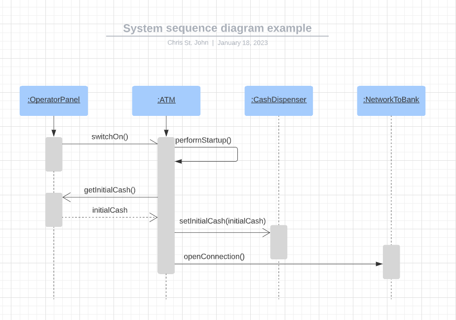
- Sequence Diagrams enrich your understanding of distributed architectures
Systems - Database UML (Unified Modeling Language) i
Visual representations of complex systems, making it easier to understand the relationships between different components and how they work together.
Communication: UML diagrams can be used as a means of communication between developers, stakeholders and other members of a project team. They provide a common language for expressing software design and can facilitate the understanding of complex systems.
Design: UML diagrams can be used as part of the software design process to model the structure, behavior and interactions of a system. They can be used to explore different design options, identify potential problems and improve the overall design of a system.
Verification: UML diagrams can be used to formally verify the design of a system, ensuring that it meets certain requirements and constraints. They can also be used to test the system's behavior, helping to identify any errors or inconsistencies.
Reusability: UML diagrams can be reused across different projects, allowing for the efficient development of new systems.
Maintenance: UML diagrams can be used to understand and maintain existing systems, making it easier to identify and fix bugs and make updates to the system.
Incorporation of design patterns: UML diagrams can be used to easily incorporate design patterns into the system.
Standardization: UML is widely accepted industry standard for modeling software systems, which allows for more efficient communication between different teams and organizations.
How to create the UML Diagram
- Determine the scope of the diagram
- Decide what aspects of the service you want to represent in the UML diagram, such as the classes, objects, and relationships between them.
- Identify the classes
- Identify the main classes or objects that make up the service, such as users, drivers, vehicles, and rides.
- Define the class attributes
- Determine the attributes that describe each class, such as name, address, vehicle type, and ride status.
- Establish relationships between classes
- Determine the relationships between the classes, such as association, aggregation, and composition. For example, a user can have many rides, but a ride can only have one user.
- Association: a simple relationship between two classes where one class has a reference to the other. It is represented as a line connecting two classes, and can have additional information such as multiplicity, navigability, and roles. For example, an association between the "User" and "Ride" classes would represent the fact that a user can have many rides and a ride can be taken by only one user.
- Aggregation: a relationship where one class acts as a container for the other class. It is represented as a diamond shape on the end of the line connecting two classes. Aggregation represents a part-whole relationship where the contained class is part of the container class. For example, an aggregation between the "Vehicle" and "Driver" classes would represent the fact that a vehicle is composed of a driver and can exist without the driver.
- Composition:a relationship where one class has a strong ownership over the other class, meaning that the contained class cannot exist independently of the container class. It is represented as a filled diamond shape on the end of the line connecting two classes. For example, a composition between the "Car" and "Engine" classes would represent the fact that a car has an engine and the engine cannot exist without the car.
- Determine the relationships between the classes, such as association, aggregation, and composition. For example, a user can have many rides, but a ride can only have one user.
- Create the class diagrams
- Use a UML modeling tool or diagramming software to create the class diagrams, using the classes, attributes, and relationships defined in the previous steps.
- Add details to the class diagrams
- Add details such as operations, constraints, and state machines to each class to further describe the behavior and interactions of the classes.
- Operations are actions that can be performed on objects of a class. To add operations, list the methods or functions associated with each class, including the name, parameters, and return type. For example, an operation for the "User" class could be "makePayment(amount: float) : boolean", which allows a user to make a payment for a ride.
- Constraints are restrictions or limitations that are placed on the values of attributes or on the relationships between classes. To add constraints, use UML notations such as stereotypes and notes to specify the conditions that must be met. For example, a constraint for the "Vehicle" class could be "make and model cannot be empty", which ensures that a vehicle always has a make and model defined.
- State machines describe the different states that an object can be in and the events that cause it to transition from one state to another. To add state machines, use UML state diagrams to represent the states and transitions of each class. For example, a state machine for the "Ride" class could have states such as "requested", "accepted", "in progress", and "completed", and transitions such as "request ride", "accept ride", and "finish ride".
- Add details such as operations, constraints, and state machines to each class to further describe the behavior and interactions of the classes.
- Refine the diagram
- Review the diagram to ensure that it accurately represents the service and make any necessary revisions.
- Present the diagram
- Present the final UML diagram to stakeholders to communicate the design of the service and to gather feedback.
Systems - State diagram
- Clarity: State diagrams provide a clear and concise way to represent the behavior of a system, making it easy to understand and communicate the system's behavior to others.
- Modularity: State diagrams can be used to model the behavior of individual components of a system, making it easy to understand the interactions between these components.
- Verifiability: State diagrams can be used to formally verify the behavior of a system, ensuring that it behaves as expected and identifying any potential errors or inconsistencies.
- Reusability: State diagrams can be reused across different projects, allowing for the efficient development of new systems.
- Debugging: It's easy to identify the bugs in the system by using state diagrams, which makes debugging faster and more efficient.
- Scalability: State diagrams can be used to model complex systems with many states and transitions, making it easy to understand and manage the behavior of large systems.
- Concurrency: State diagrams can be used to model systems with concurrent processes, making it easy to understand how these processes interact and how they are coordinated.
Resources
Diagram tools
- LucidChart
- Draw.io
- Whimsical
- Visio
- Diagrams.net
- Gliffy
- Network Topology Mapper (NTM)
- PlantUML
- translate CLI/text instructions to architect diagrams
- https://plantuml.com/en/starting
- docs: https://plantuml.com/en/guide
- IBM Architecture Room Live
Diagram Learning Sources
- UML Diagrams Full Course (Unified Modeling Language)
- How to Make a UML Sequence Diagram
- UML Graphic Notation reference
- Entity Relationship Diagram (ERD) Tutorial - Part 1
- Architecture diagram examples:
- Importing your AWS Cloud Architecture into LucidScale
- Importing your GCP Cloud Architecture into LucidScale